we will focus on creating the first draft, going through the steps one by one. It is crucial to go through this stage step by step. I have highlighted the most important points, which I covered in detail earlier, while we have already examined the key aspects of the environment. The following tabs also offer additional options, which will be presented here.
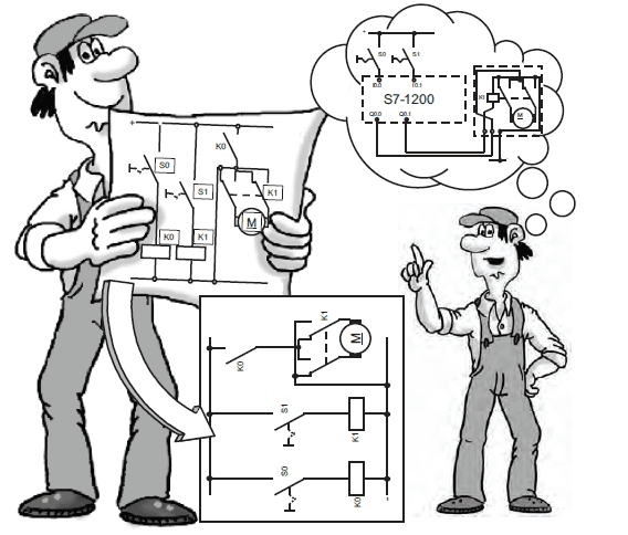
What does the project involve?
0. Algorithm for machine/line operation (written on a piece of paper)
1. creation of the project in the development environment
2. Hardware configuration
a) Selecting a PLC (e.g. S7-1200)
(b) Assignment of an IP address (if applicable)
c) Address setting for digital inputs and outputs (if applicable)
(d) Other settings (if any)
3 Writing programme code
-Creation of symbolic names for digital inputs/outputs (according to point 2c)
-Input and output tests (IO test)
-Coding
4. PC-PLC connection configuration (when using the actual PLC)
5. download (uploading data to the controller)
6. tests and possible amendments
-
Before we create the first project, I have prepared a step-by-step breakdown, showing how the working procedure from the concept phase to the creation of the project should look like. The next steps are marked, and it is a good idea to start by preparing an algorithm that defines how the project should work. This algorithm can be general at the beginning, but will become more and more detailed over time. It is useful to have an idea at the outset of how we want the project to work.
We then proceed to the stage of putting the project down in the environment. This project consists of two main parts: the hardware configuration and the software part.
Here, in tab two, we focus on the hardware configuration. This configuration is divided into several smaller parts. The first step is to add a driver. We need to select the appropriate driver from the available options. In this lesson, we will focus on the 1200 controller. If you are working on an actual controller, you may need to give it an IP address, which is sometimes required by a customer project. If there are no specific IP address requirements, the controller usually has a default address of 192.168.0.1.
Another important point (2c) is the setting of addresses for inputs and outputs. This issue often causes difficulties for beginners because it requires an understanding of addressing. The addresses should match the design assumptions, which is crucial for the subsequent programming of the controller. For more advanced applications, point 2d involves additional settings in the PLC. These are advanced configurations that can be customised according to the needs of the project.
It is worth noting that more advanced settings can be configured later, with the initial focus on running and testing the basic functions. We can approach the configuration in stages, checking the operation of each functionality before moving on to the next. Such a step-by-step procedure makes it easier to identify possible problems and enables more effective correction.
Point 3 covers the creation of symbolic names, i.e. links between the address we have configured in the hardware part and a name to make it easier to understand. This is a preparation for easier programming. In the next step (3B), an important step is to test the inputs and outputs to check that all signals are correctly reaching the controller. It is worth verifying the correct operation of sensors, buttons and other actuators, especially when working on real hardware.
If you are working on real hardware, you will also need to ensure that the computer is properly prepared and the interfaces are set up to allow for a correct connection (point 4). If you are working on a virtual controller, this step is usually automatic, but it is worth making sure that all settings are correct. If necessary, you can adjust the settings in the control panel, under the pg-pc tab.
We then move on to step 5, which involves the download process, i.e. uploading the prepared programme from the PC to the controller, whether it is a real or virtual controller. This stage is important because it allows us to input our work into the controller so that it starts to perform according to our design intentions.
Point 6 covers the testing stage, where we check that our work works as designed. If we encounter errors, corrections need to be made. This process may require going back to the coding stage, but it is important to make corrections in small steps, testing each change. The key is to have an algorithm and to go through each task consciously.
When we start working with PLCs, it is important to have a list of next steps prepared. Throughout the course we will progress gradually through the steps, some of the more advanced ones appearing in later lessons.
LAD programming language (ladder)
During the first project, we will be using the LAD (ladder) language, which is dedicated to electricians.
Although the S7 1200 controller allows programming in three languages (LAD, FBD, SCL), we will mainly focus on the graphical language, specifically Ladder. This language is the default for the OB1 file, which we will learn more about in the following sections of the course.
Project premise
Here we see the view of the development environment, i.e. the Project View. The easiest way to navigate this environment is to use the numbered points that mark out the key steps. We start with function number one, where we create a new project in the first step.
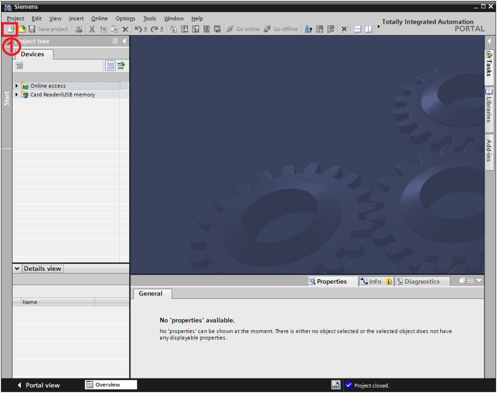
To do this, we click on the card icon marked with a red rectangle. Once clicked, a new window will open where we can initiate the project creation process.
Name of the project
W oknie 'Create New Project’, wpisujemy nazwę projektu (patrz pole 'Project Name’), na przykład 'First Project’.
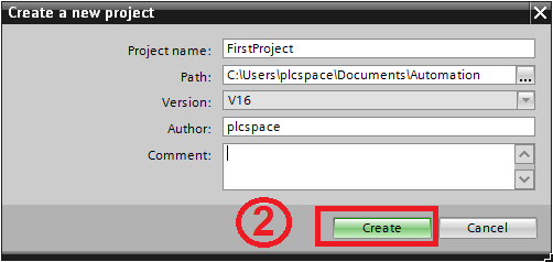
Kolejne pole to ścieżka, w której projekt będzie zapisywany. Domyślnie projekty zapisywane są w folderze 'My Documents/Automation Projects’. Możemy pozostawić tę ścieżkę lub utworzyć nowy folder w celu organizacji projektów. Kolejne pola obejmują wersję TIA Portal, autora oraz opcjonalny komentarz.
Następnie klikamy przycisk 'Create New Project’, zaznaczony numerem dwa na czerwonym tle. Teraz przechodzimy do konfiguracji sprzętowej, co stanowi kolejny etap po utworzeniu projektu. Warto podkreślić, że proces tworzenia projektu może chwilę potrwać, dlatego potrzebujemy odrobinę cierpliwości, zwłaszcza gdy niektóre zadania w TIA Portal wymagają więcej czasu. Po utworzeniu projektu, pojawi się widok TIA Portal.
Stage - hardware configuration
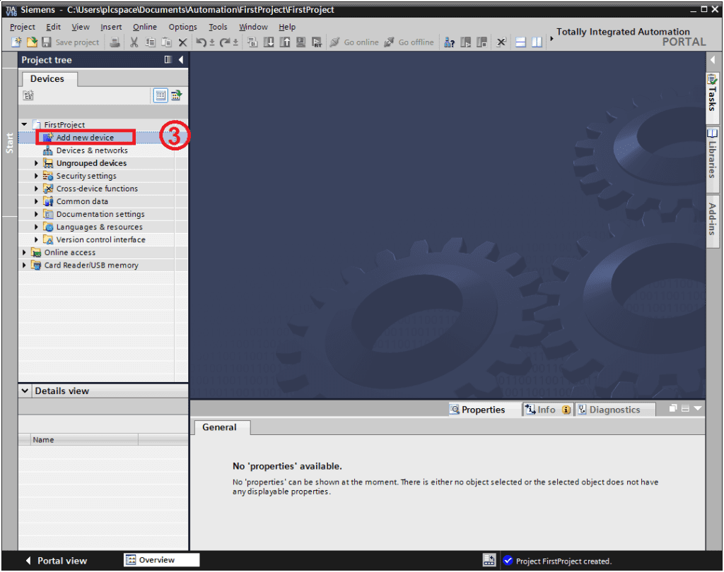
Podczas prezentacji widzimy kolejne zadanie, a mianowicie dodanie nowego urządzenia, co stanowi trzeci krok w procesie. W drzewie projektu mamy już utworzony nasz projekt, który zazwyczaj jest rozwinięty. Przy nazwie projektu, na przykład 'First Project’, widzimy czarny trójkąt. Możemy go rozwinąć lub zwinąć, co działa również dla innych folderów, takich jak urządzenia. Klikając na trójkąt, możemy schować lub rozwijać widok danego obiektu.
Adding a device
Teraz przechodzimy do dodania nowego urządzenia. W drzewie projektu klikamy na 'Add New Device’.
Warto zauważyć, że jeżeli pracujemy na licencji testowej, może pojawić się okno związane z automatycznym managerem licencji, takie jak 'STEP 7 Basic’. Tutaj wybieramy odpowiednią licencję, na przykład 'STEP 7 Professional’, która jest podświetlona na niebiesko.
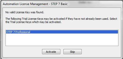
Po zaznaczeniu klikamy przycisk 'Activate’, co daje nam 21 dni na pracę w TIA Portal z licencją Trial
CPU selection
Następnie przechodzimy do kolejnego okna, 'Add New Device’, klikając czerwony przycisk, co oznacza czwarty krok
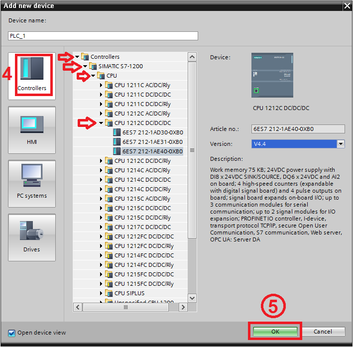
W folderze 'Controllers’ rozwijamy odpowiednie foldery, a następnie wybieramy CPU z rodziny simatic S7 1200, na którym będziemy pracować. Pamiętajmy o rozwinięciu CPU przy jednostce centralnej, która zawiera podprogramy z rodziny 1200.
Now we need to choose the model of controller on which we will work on the project. I have chosen a 1212 DC DC CPU, which is a slightly higher unit, but within the smaller units, and sufficient to run this course. We will be working on a virtual controller, so you can choose any controller to work through all the tasks in this course. However, if we have an actual controller available, we need to choose exactly the hardware we have physically.
To find out what equipment we have based on the order number, these numbers are visible in the equipment selection window. The order number, highlighted here, e.g. 6ES7 212, is located under the bottom flap on the right side of the controller. Expanding the CPU 1212 DC-DC-DC folder, we see three generations of controllers available for purchase. For the purposes of this course, I have chosen the third generation, which is the latest.
If we do not plan to buy a new controller, but only want to work on a virtual one, we can choose any generation. For the virtual controller, I will focus on the third generation. Once the controller is selected, the description box on the right provides key information about the controller, such as the number of built-in inputs/outputs (8 inputs and 6 outputs in this case) and working memory information (75 kilobytes).
This information is important especially at the initial programming stage, allowing us to adapt the hardware to our needs and see which CPU to choose depending on the type of project. Fifth point. I suggest that at the beginning you carefully choose the same model of controller that I will be presenting in this course, and also work on a virtual controller in PLC SIM. These items will be useful if you are testing your application, even if you plan to work on the actual controller. There is some functionality here that is very helpful when testing, which will also be covered in the course.
Device configuration
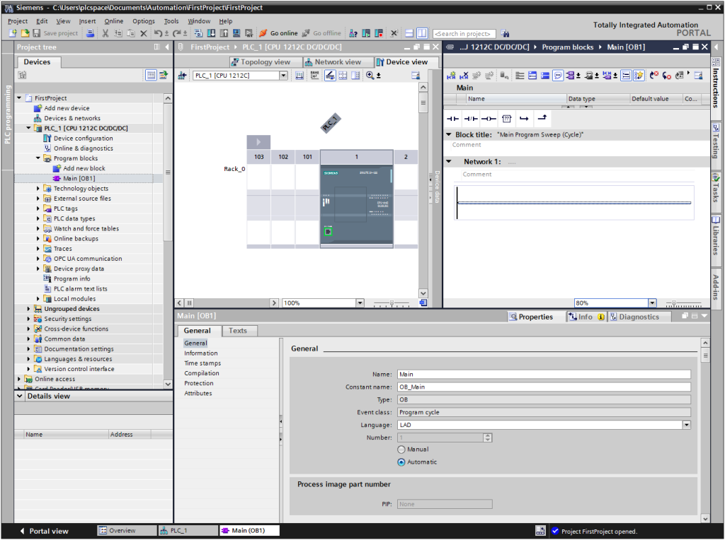
We now move on to the next step, where the hardware configuration view of the driver appears by default. This is set by default when adding a new driver, and I have highlighted the most important places to note in the TIA Portal hardware configuration view.
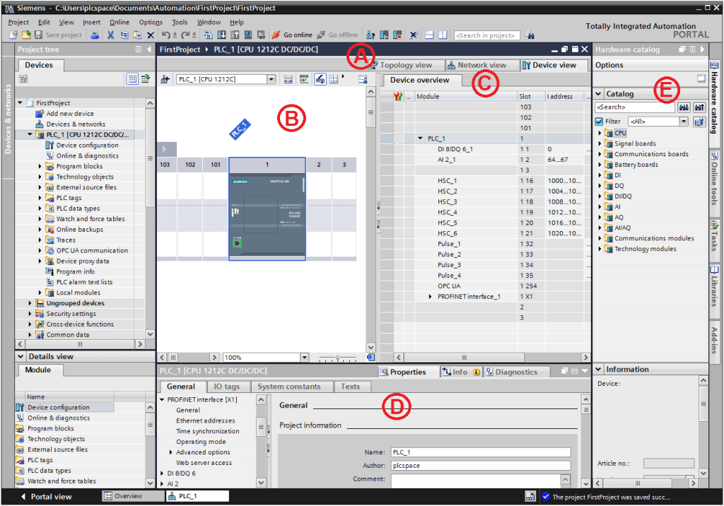
As far as Point A is concerned, we have three tabs: Device, Network, and Topology. The Device tab is for settings relating to the PLC itself. The next tab, Network, allows us to configure network settings, which is important when we want to connect the controller to another network device. The last tab, Topology, is dedicated to the physical connection, specifying the cable locations, slots, and RJ45 ports on the device. In this course, we will mainly use the Device tab, which is necessary for setting up addresses. Although addresses can also be configured in other places, we will discuss this later. In general, the Device tab covers a summary of addressing at this level.
Point B shows a view of the virtual bus on which devices such as the PLC (CPU) and additional modules are mounted. Here there are virtual slots where modules can be mounted. The hardware configuration is built according to the actual layout, and everything must match. This hardware configuration is related to tab B, which I mentioned earlier, and in this phase we mainly focus on addressing.
It is worth noting that the items indicated only apply to the Device tab, which is key in the context of addressing at this level of hardware configuration.
Default I/O addressing
The most important aspect in this phase is addressing, which is a key starting point for many students, especially at the beginning of their automation-related learning. Addresses are essentially assigned to the signals connected to the controller's inputs and outputs, which we will discuss in more detail later.
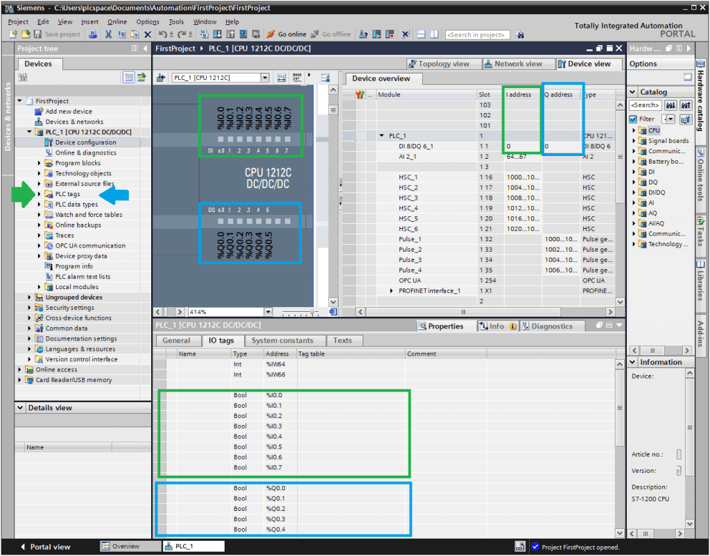
On the Device View, we can see where the inputs and outputs are located. The inputs are highlighted in green and their addresses are visible when we zoom into the workspace. If we mark the controller as Focus, the addresses associated with the outputs, highlighted in green, appear in the inspector window on the Properties tab. In the PLC, we have a compact unit, characterised by a TSO unit, as well as inputs and outputs. The addresses for the input signals are shown in green and those for the outputs in blue. A green arrow is visible in the project tree, symbolising the addresses needed for the PLC. We will focus on this later in the course. The PLC has inputs and outputs, which is typical of compact controllers. The addresses for the outputs are set to 0 by default, as are those for the inputs. However, these addresses can be adjusted, which we will discuss in the following sections.
Stage - Software
We now move on to the Software area, the software configuration stage. We have now completed the hardware configuration stage.
The first step is to run a simple programme. We leave the default addresses as they are. In the Software area, we see the link to Hardware and the addressing. It is crucial that the addresses are set correctly so that the hardware configuration is correct, allowing us to move on to the Software stage later.
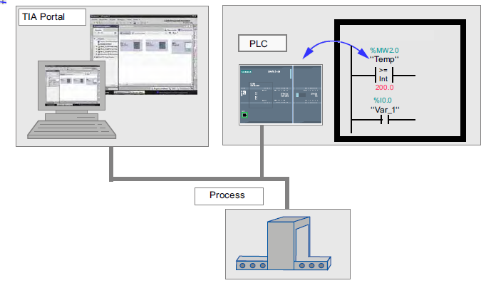
In the figure we can see how this part (Network) is related to our hardware, indicated by the black box. The arrow illustrates the relationship between the hardware and the programme code.
Block OB1
We enter the programme code into the organisational block OB1, which we see on Programme Blocks. We click on Main OB1 to go to the place where the programme code can be entered.
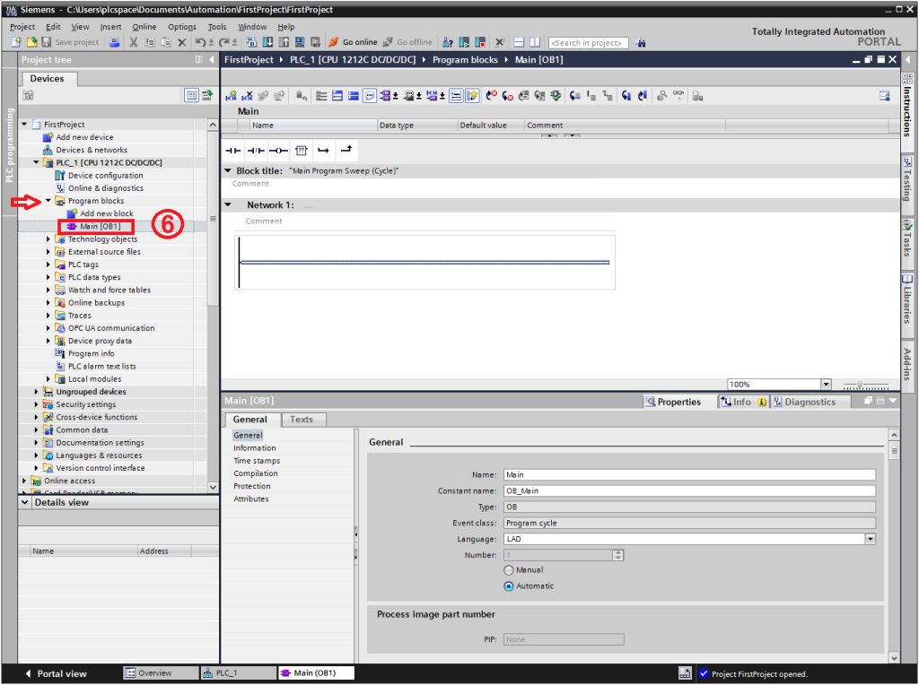
Next, we move to step six, where we click on Main OB1. In the work area, we see the programme code editor.
Editor
I have highlighted the most important elements of this editor. The icon bar contains shortcuts to the most frequently used functions, such as adding another line of code or adding another network. If we want to add a new network, we use the Network icon.
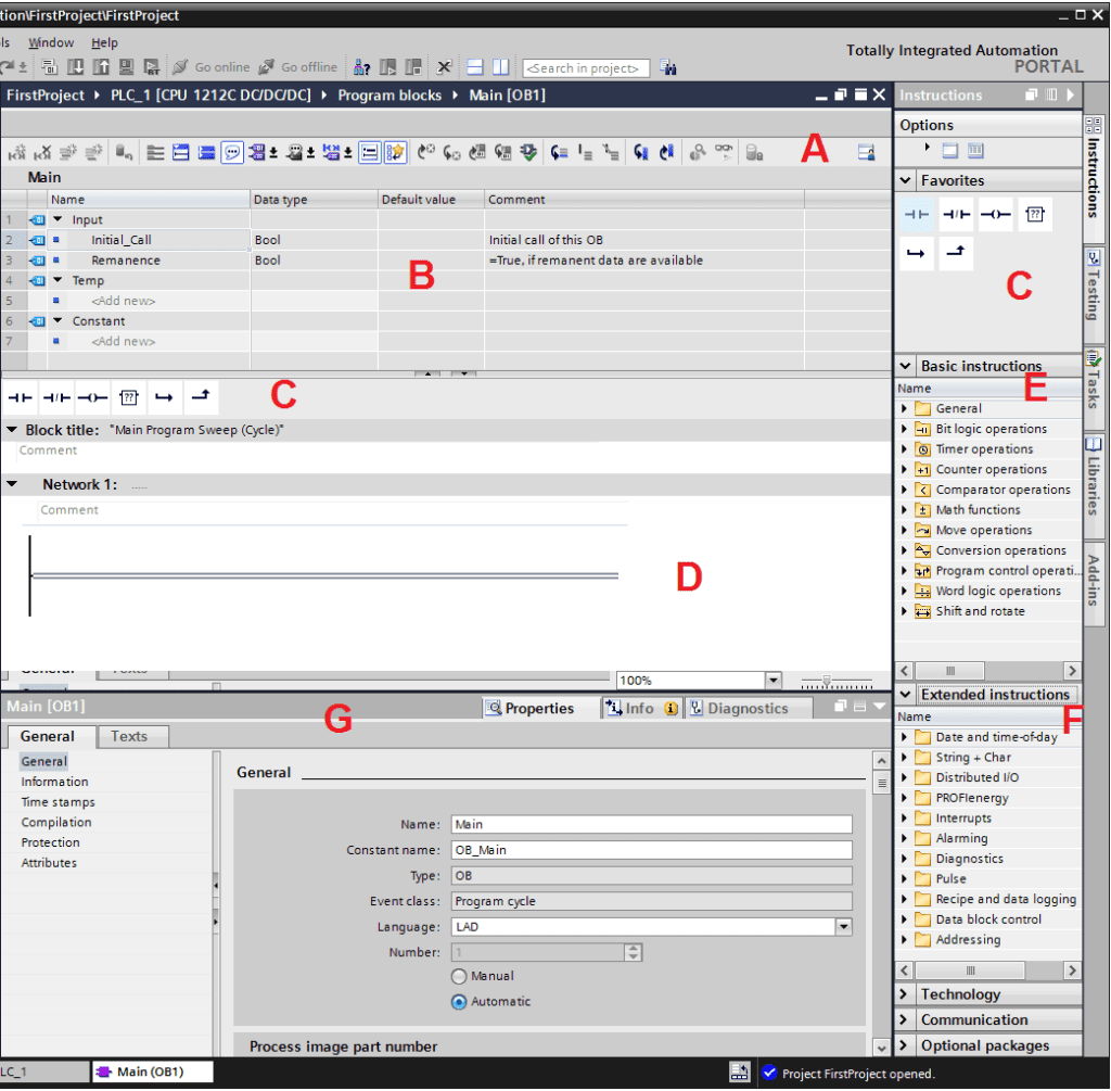
In the interface area, depending on the block, parameters and variables can be opened. The Interface section is a bar of favourite instructions, and the Favorites Instructions section makes it easy to add frequently used instructions. Icons in the Instructions tab facilitate access to instructions. In the Function (F) tab, we have access to extended instructions. Point G is the Inspector window, where we see the properties of the block we have selected. This is the first project that has gone through the stages of hardware configuration and where to write the program code.